
Pandemic - The Arcade-Style Shuffleboard
The Dutch Shuffleboard
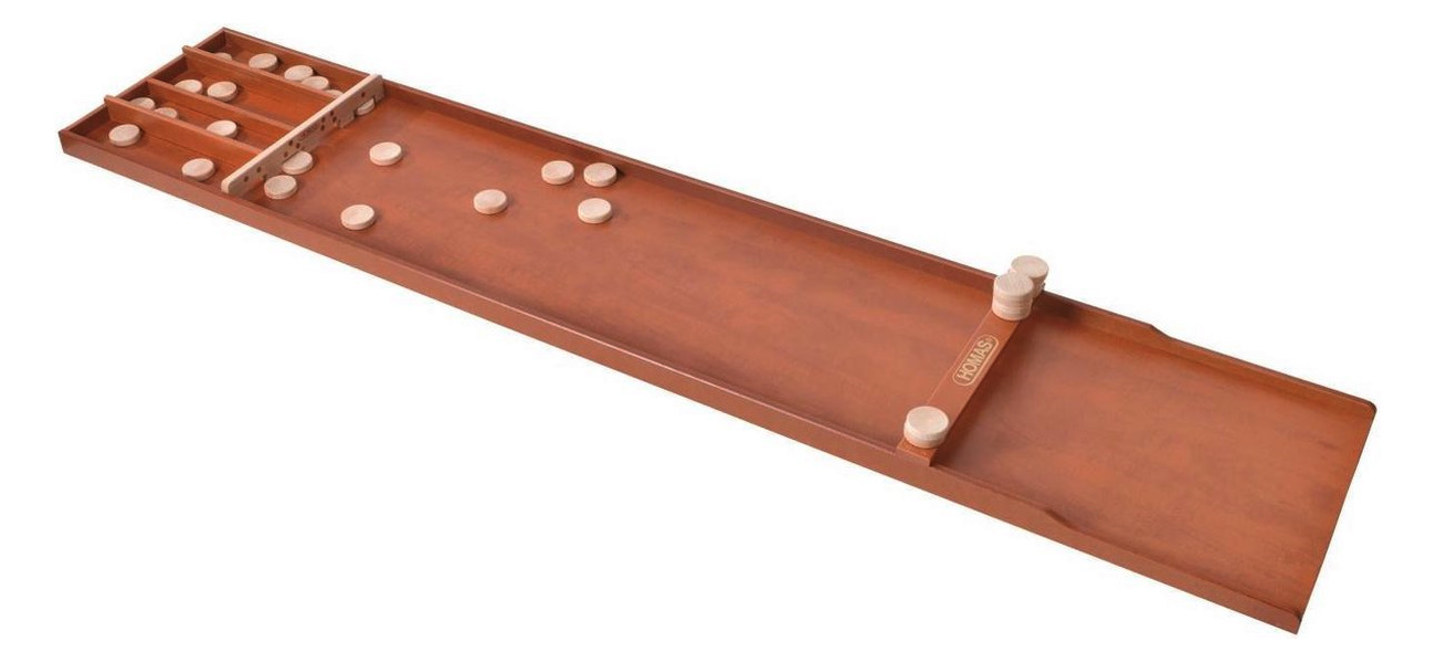
A Dutch shuffleboard is a long wooden board with 4 gates (holes) at the far end. The goal of the game, called "sjoelen", is to shove 30 wooden pucks into those gates. A number above the gates indicates the score you get when your puck enters that gate (1 - 4). But you also get 10 points extra when you get one puck in every gate for a total of 20 points. When all pucks have been shoved, the player takes back the pucks that didn't enter any gate for the next round. The game ends after 3 rounds.
In the Netherlands, this is a classic family game that is played by young and old in every generation (mostly in the days when there was no XBox or Playstation). Have a look at the shoveling moves of Siem Oostenbrink, who is 3 times world champion!
The Concept
One day I woke up with this idea to turn a classic Dutch shuffleboard into a flashy, arcade-style game, the same style that pinball machines have. This is what I had in mind:
- LED Matrix display with text and flashy animations.
- Sound effects.
- Illuminated buttons.
- Score counting.
Something I also considered, was bringing pucks back to the front automatically. But that idea was short lived as it was clearly going to be very complex.
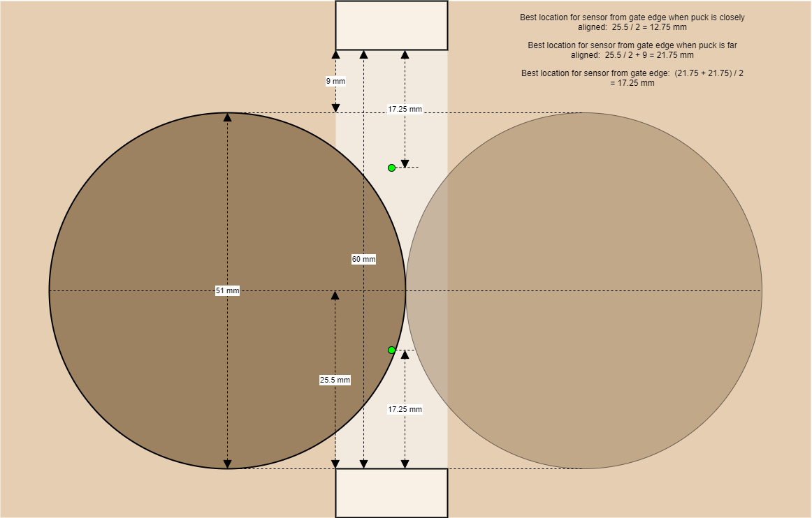
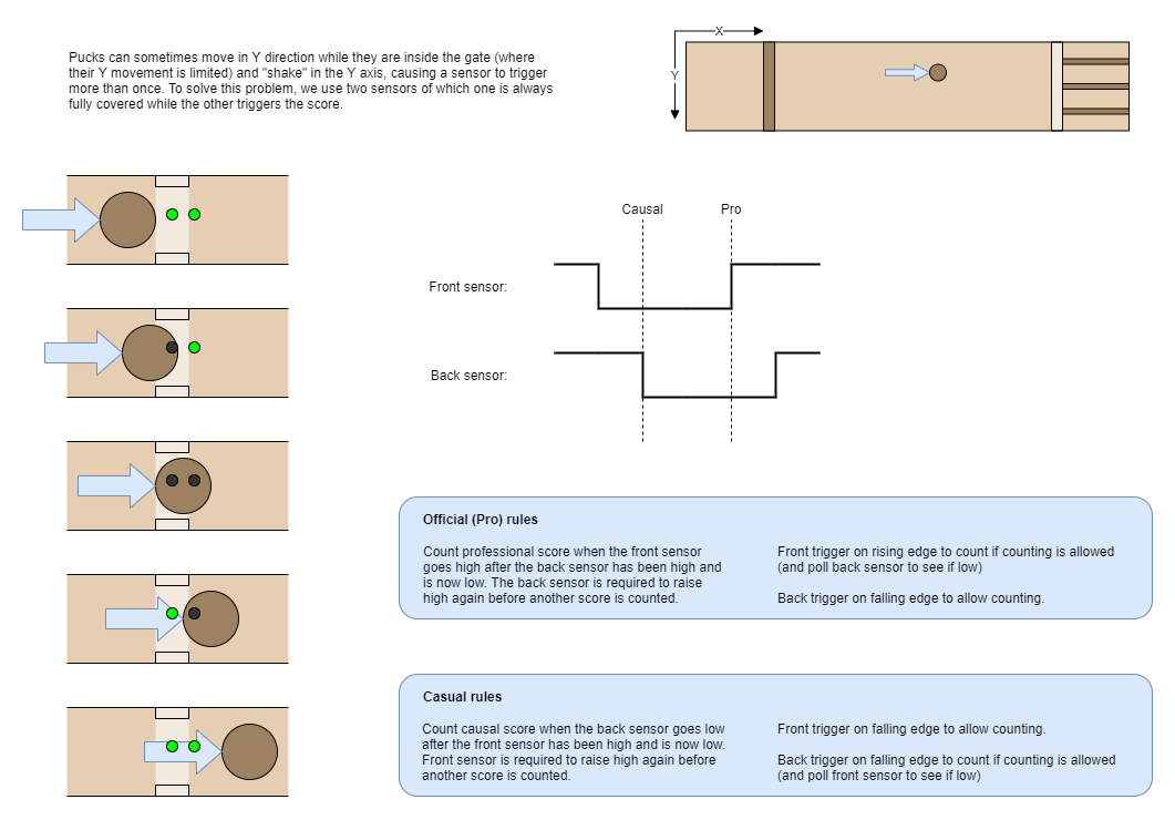
The idea for the score counting was to do this with infrared LEDs and sensors. I hadn't done this before and wasn't sure if it would work. First I calculated what the best position for the sensor would be to see pucks pass by the gates. In the middle is not a good idea because two pucks can push each other causing them to touch and the sensor can't tell the difference between the two pucks. Also, along the sides of the gate is not a good idea because there is some space between the diameter of the puck and the width of the gate. So a puck could pass unseen.
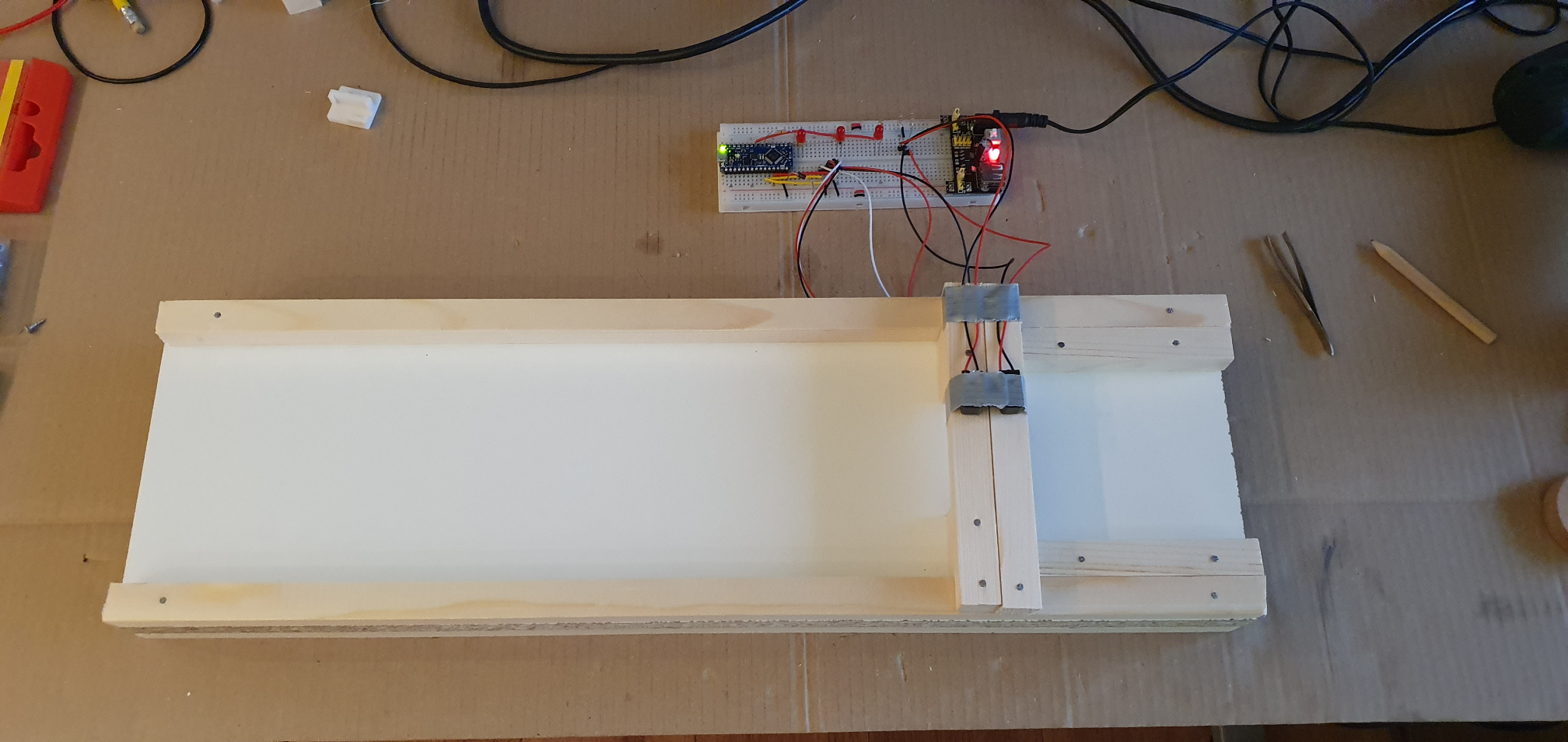
To make sure that this will work, I made a test setup. This consists of a mini shuffleboard with 1 gate that is the same width as a normal gate. An Arduino with an LED and a sensor should detect the puck.
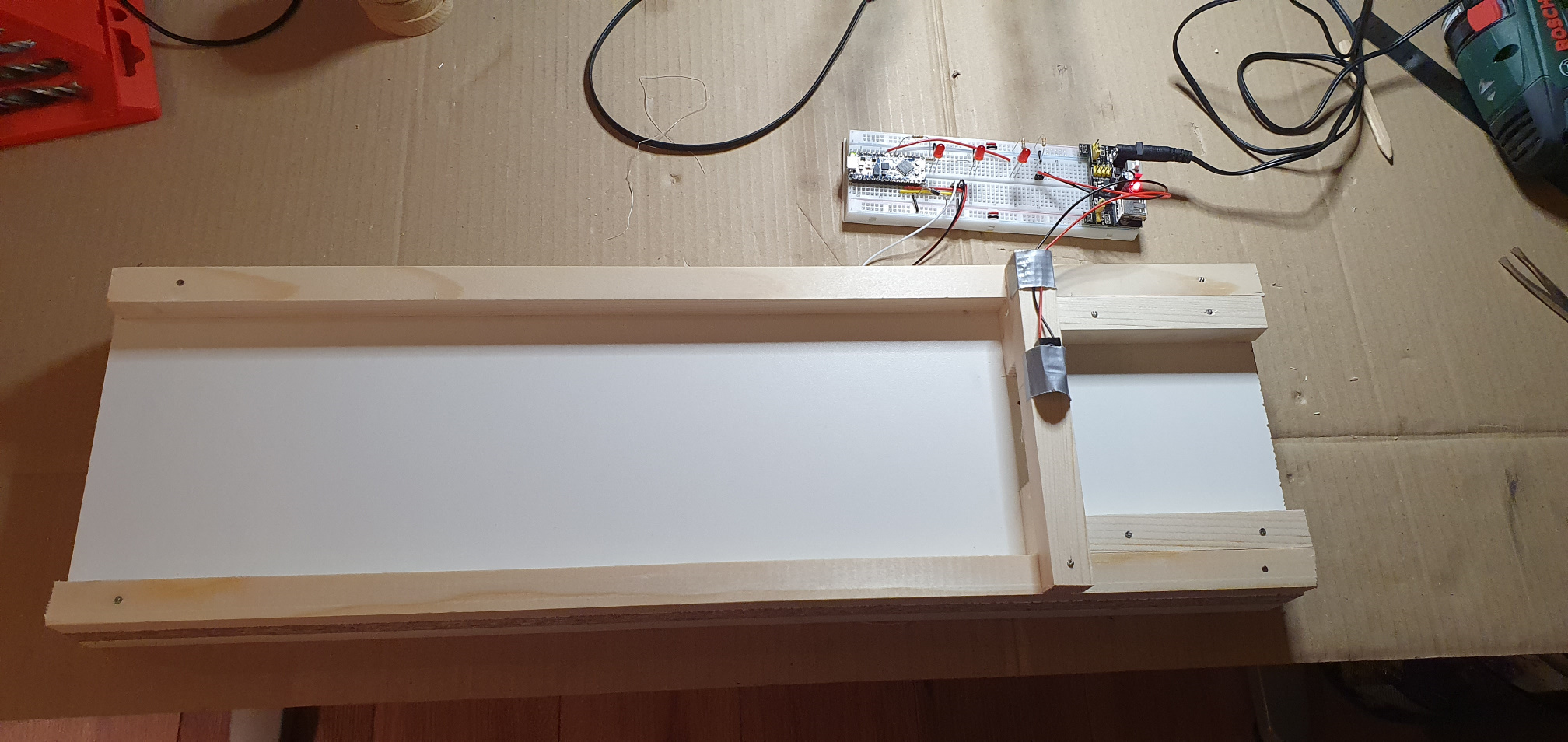
The test showed that the pucks are sometimes counted more than once when they go through the gate. This happens because the pucks can still move along the "Y" axis halfway into the gate and break the sensor beam more than once. The solution for this was to use 2 sensors in succession.
The Design
Because I only have 1 shuffleboard, I work as much as possible according to the waterfall model (first-time-right). This means I need to have a pretty good design before I start sawing and drilling.
For the design I chose to use Fusion 360. This is because it is free and my colleagues also used it (and praise it). I had never used it before, but with tips from my colleagues I came a long way. So I accurately measured the original shuffleboard and made a 3D model of it.
Underneath the shuffleboard, I added a wooden housing which makes the whole thing 5.5 cm higher. This gives room for the electronics, the speakers and the buttons. The 5.5 cm was chosen partly based on a minimum height that I need for the electronics and partly on the size of the wooden planks I could find.
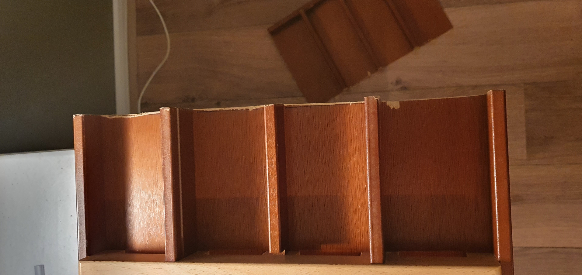
One of the downsides of the original shuffleboard is that the slots behind the gates don't offer enough space to store pucks side by side. Someone should always be stacking pucks behind the gates to keep the slots from filling up. I solved this by removing a large part of the slots (about 15 cm behind the gates) and letting the pucks fall into a bin. Thanks to the extra 5.5 cm height, this was easily possible.
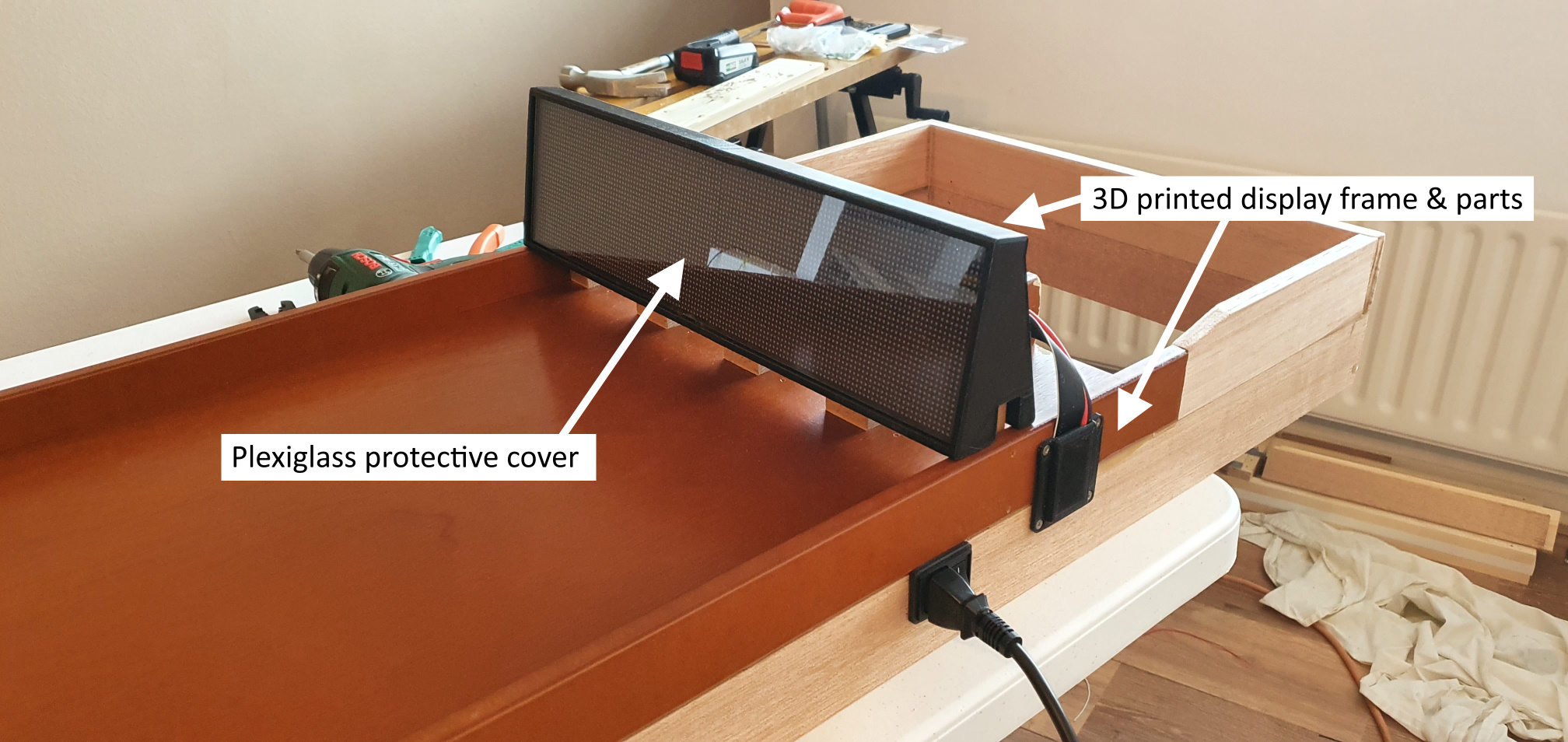
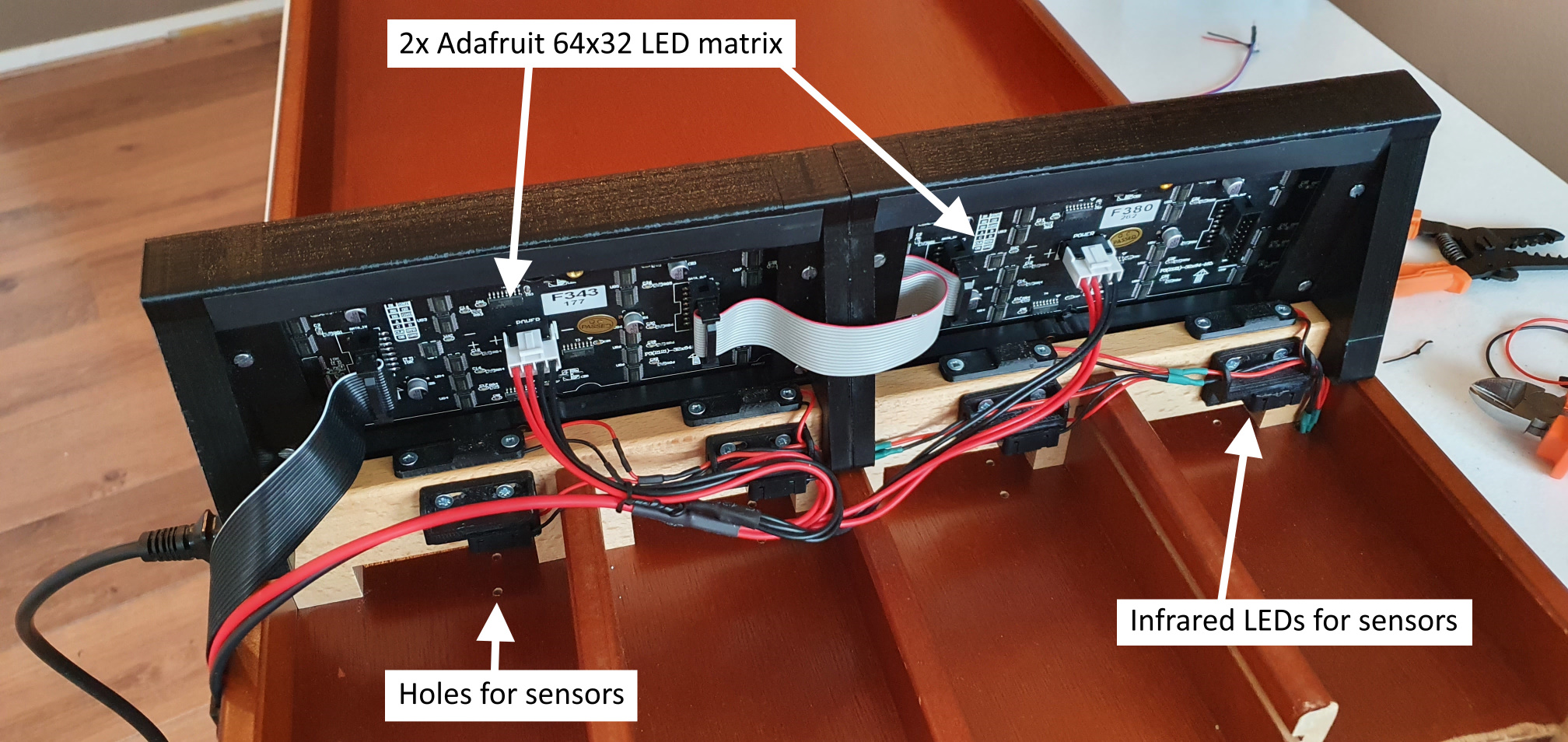
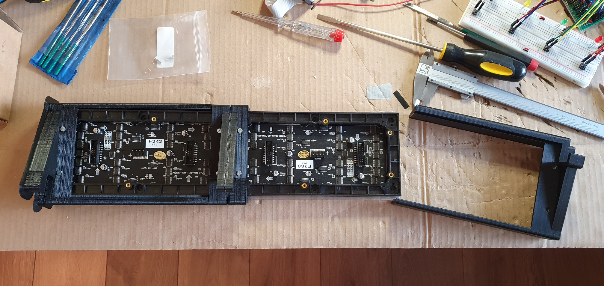
I wanted the display to sit above the ports, so that the display can also "point out" the ports where you need to score. That also happens to be a nice distance for the player to see the display well. I have chosen 2 Adafruit LED Matrix displays of 64x32 pixels each for a total size of 128x32 pixels. These just fit inside the width of the shuffleboard itself, a perfect size!
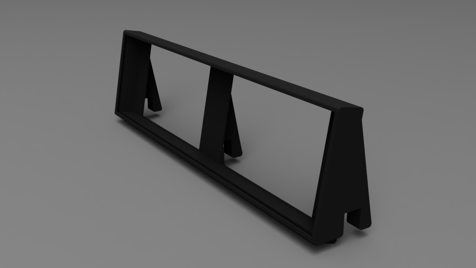
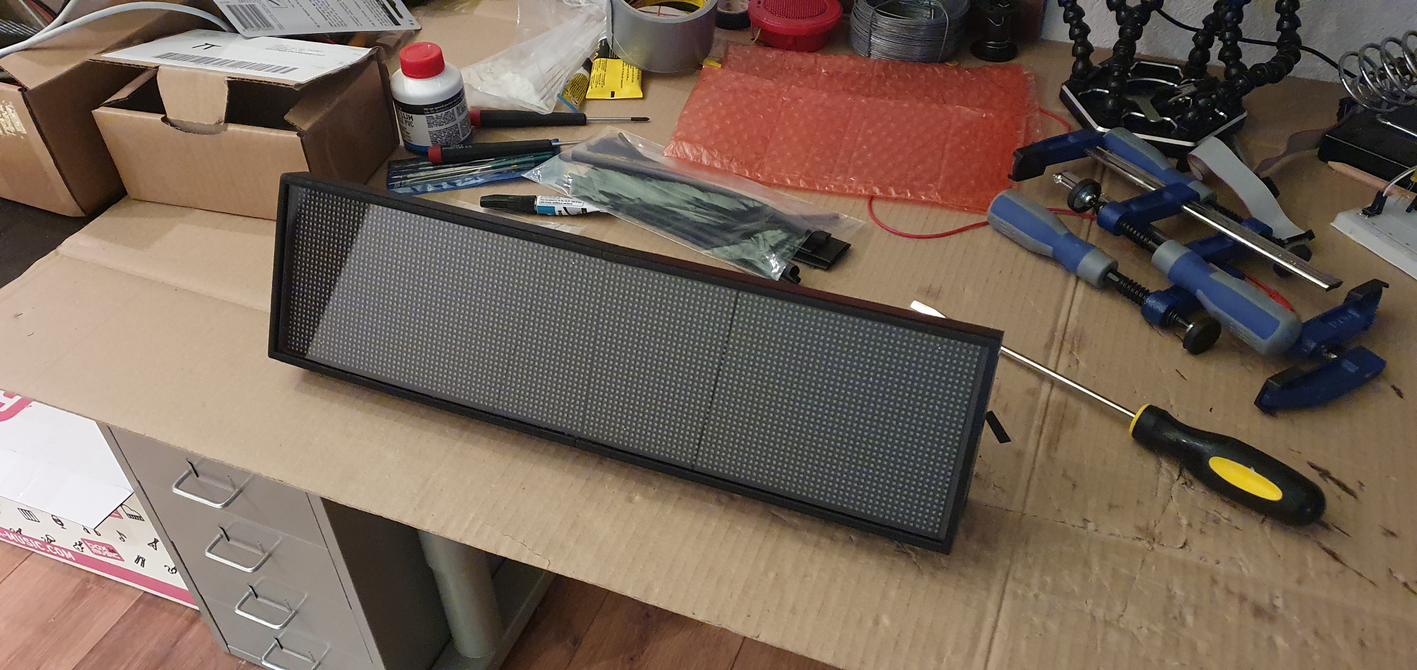
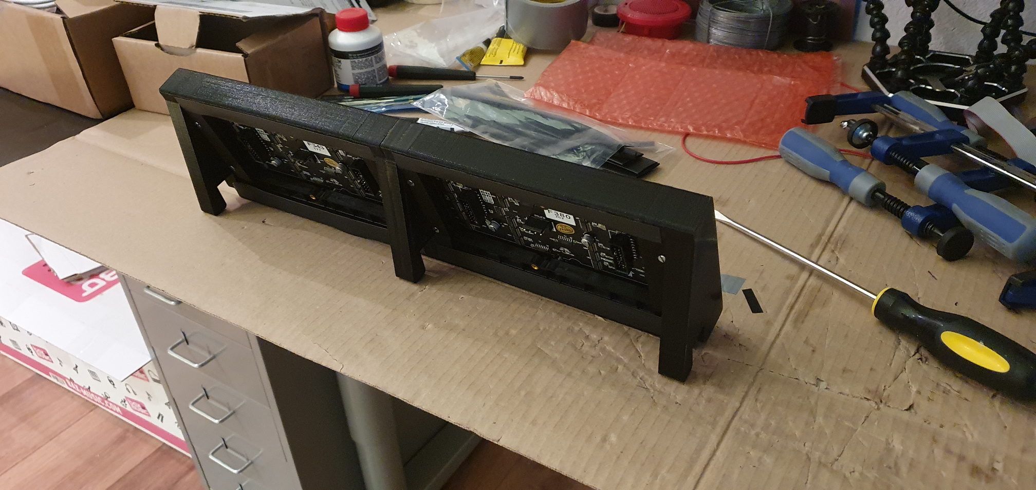
To make it nice, I will print a plastic frame in which they fit neatly. The frame is designed to sit loosely on top of the ports so that the entire display can be easily removed for transport. There is a slot in the front of the frame for a plexiglass sheet that protects the LEDs from flying pucks. The display is tilted 10 degrees backwards for better visibility from the player's position. The bottom also slopes so that it nicely overlaps over the original dots above the ports (and this gives extra stability).
I also mapped out the electronics and thought about how they work together. For the main computing I use a Raspberry Pi. For controlling the displays, I used an Adafruit Matrix Raspberry Pi HAT. This seems fitting, as the displays are from Adafruit as well. The HAT uses almost all GPIO pins (including all PWM pins) and the software library for this also uses an internal timer that is normally used for the standard audio output. This means that there are no GPIO pins left for the sensors and I have no audio output.
I therefore connect the sensors to an Arduino (Nano Every, but an Uno would do as well). The Arduinuo is dedicated to reading the IR sensors in real-time, so that every fast movement is picked up. The Arduino creates simple messages that are sent to the Raspberry Pi via the serial interface (over USB). These messages do not have to be picked up in real-time. There are 10 infrared LEDs, 2 of which are high power, to illuminate the sensors. Together, these require too much power to pull from the (USB-powered) Arduino. That's why I feed them directly from the PSU. They will be continuously lit (which reduces the lifespan), but I can always replace the LEDs if needed.
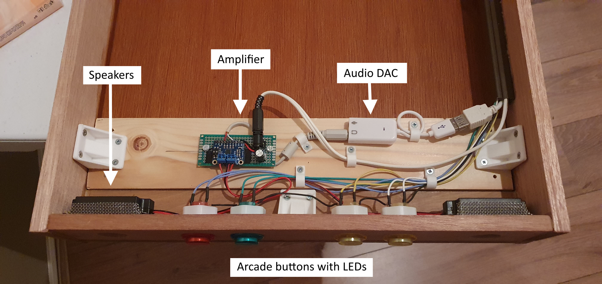
For the audio I connect via USB an audio module (PCM DAC chip) which generates an analog output, which I then pass through a small Adafruit MAX98306 amplifier for the 3W stereo speakers.
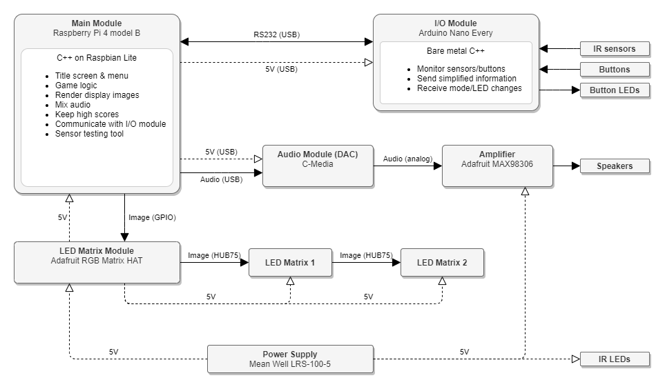
The 2 displays together consume (when all LEDs are on) a small 16A at 5V! So I need the Mean Well LRS-100-5 to generate 1.21 Gigawatt at least 80W just for the display and some more for the other components. Usually, not all the display LEDs are on (white at full brightness), but better safe than sorry.
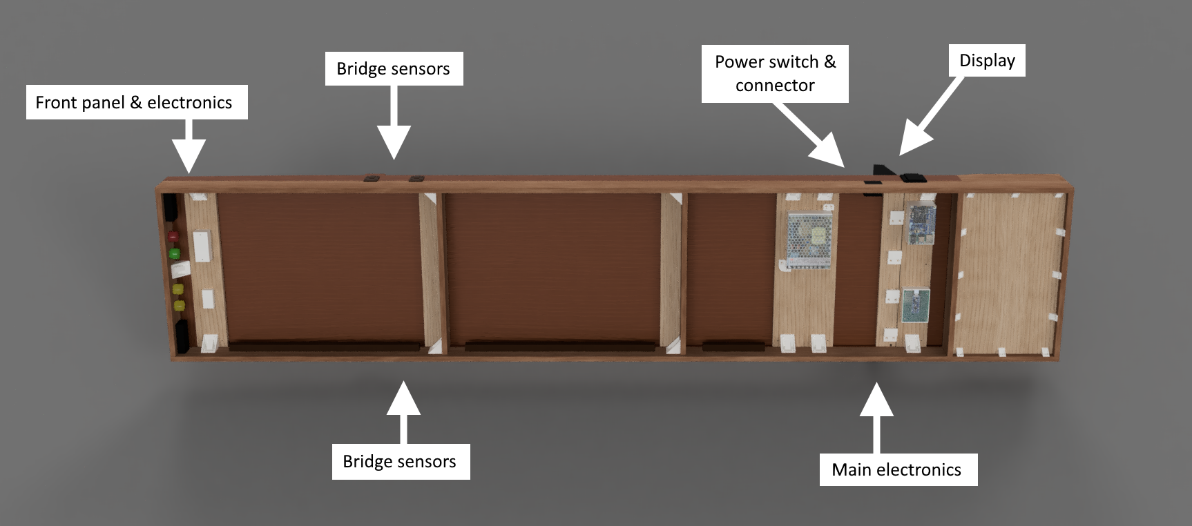
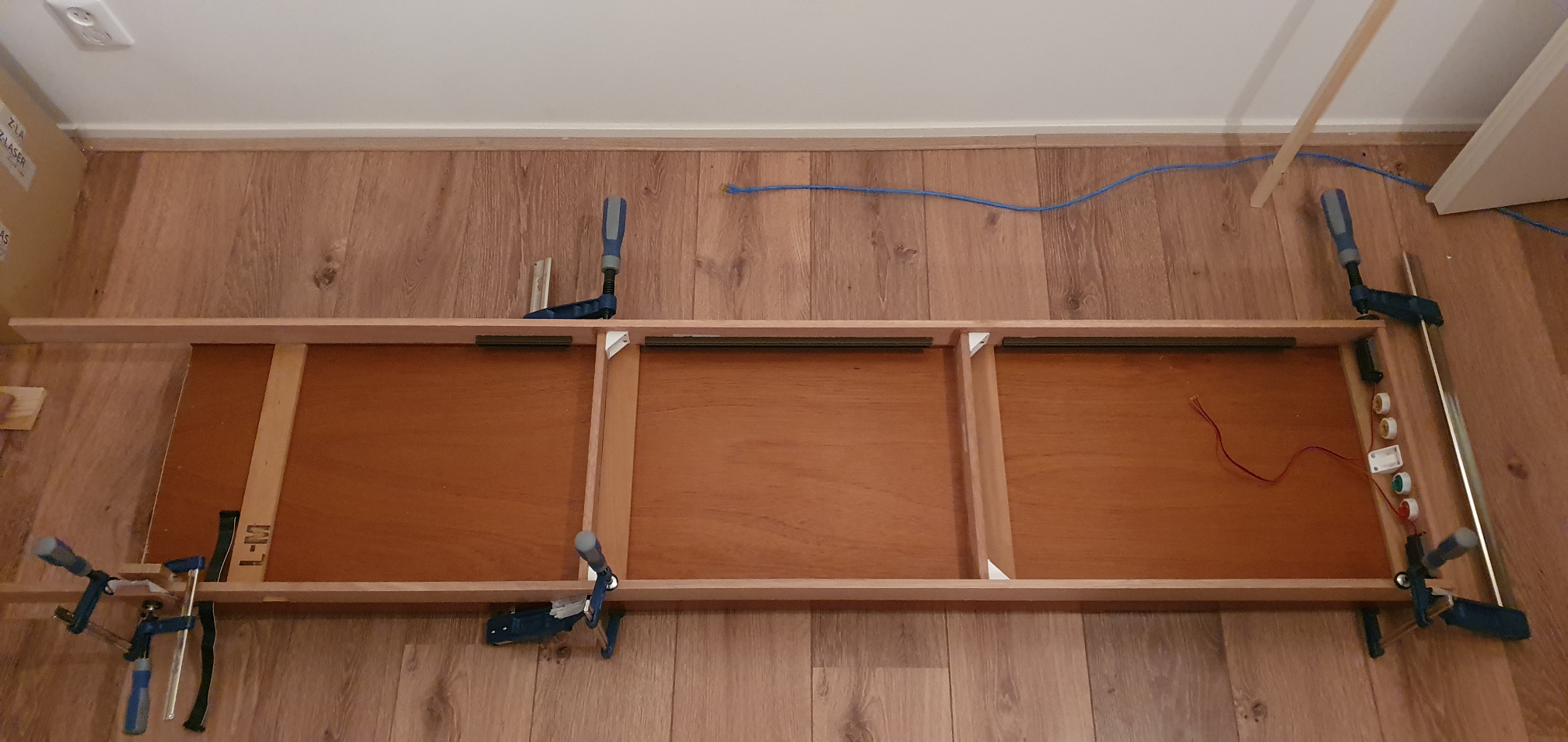
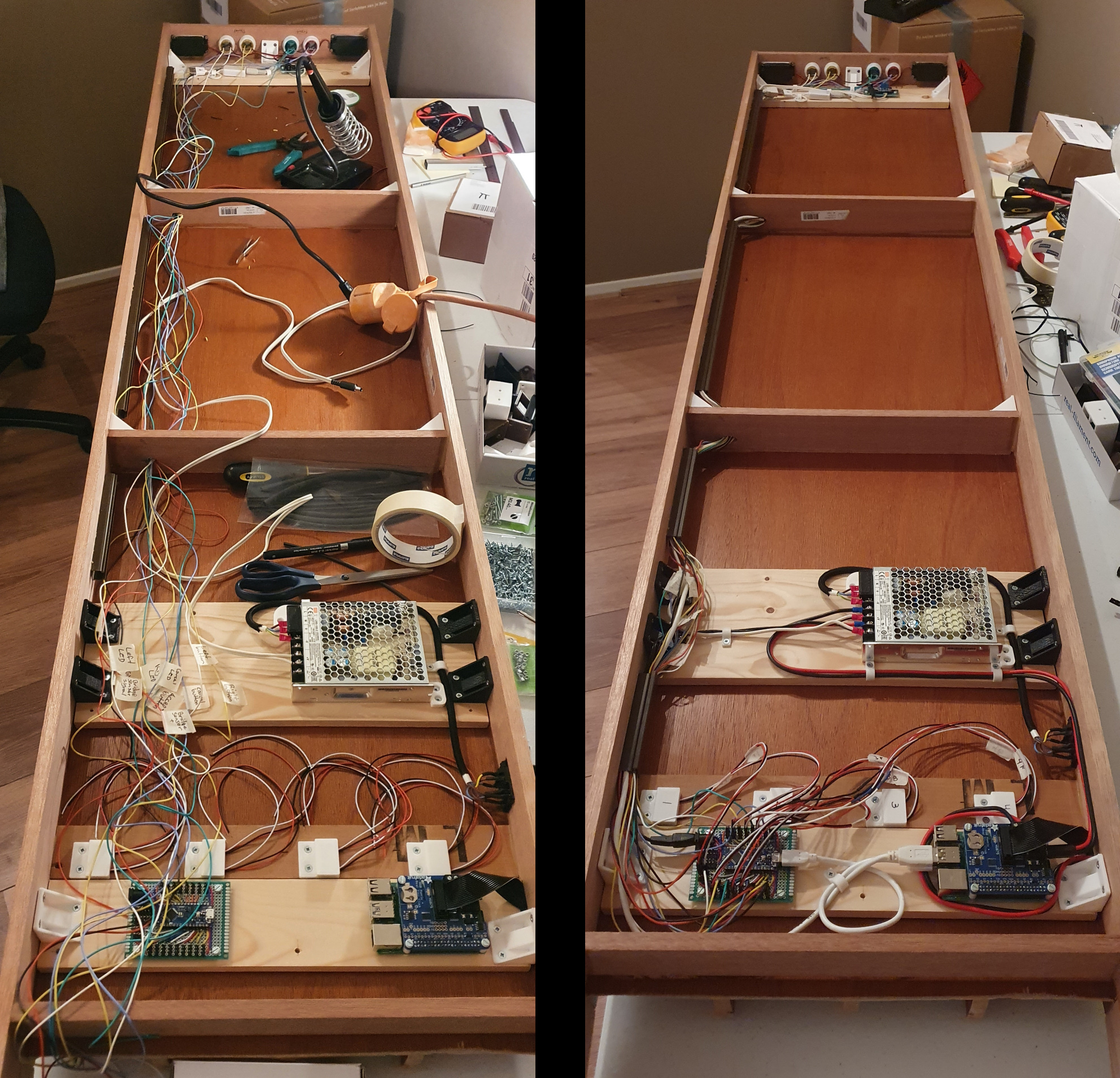
I have given everything a place in Fusion 360 and thought about possibilities for repair if necessary. The electronics are therefore on separate slats with T-nuts under the board and can always be unscrewed. Below is an overview of the bottom and detail photos of different parts.
The Construction
After a lot of designing, puzzling, searching, fitting and measuring, it is finally time to actually build the device.
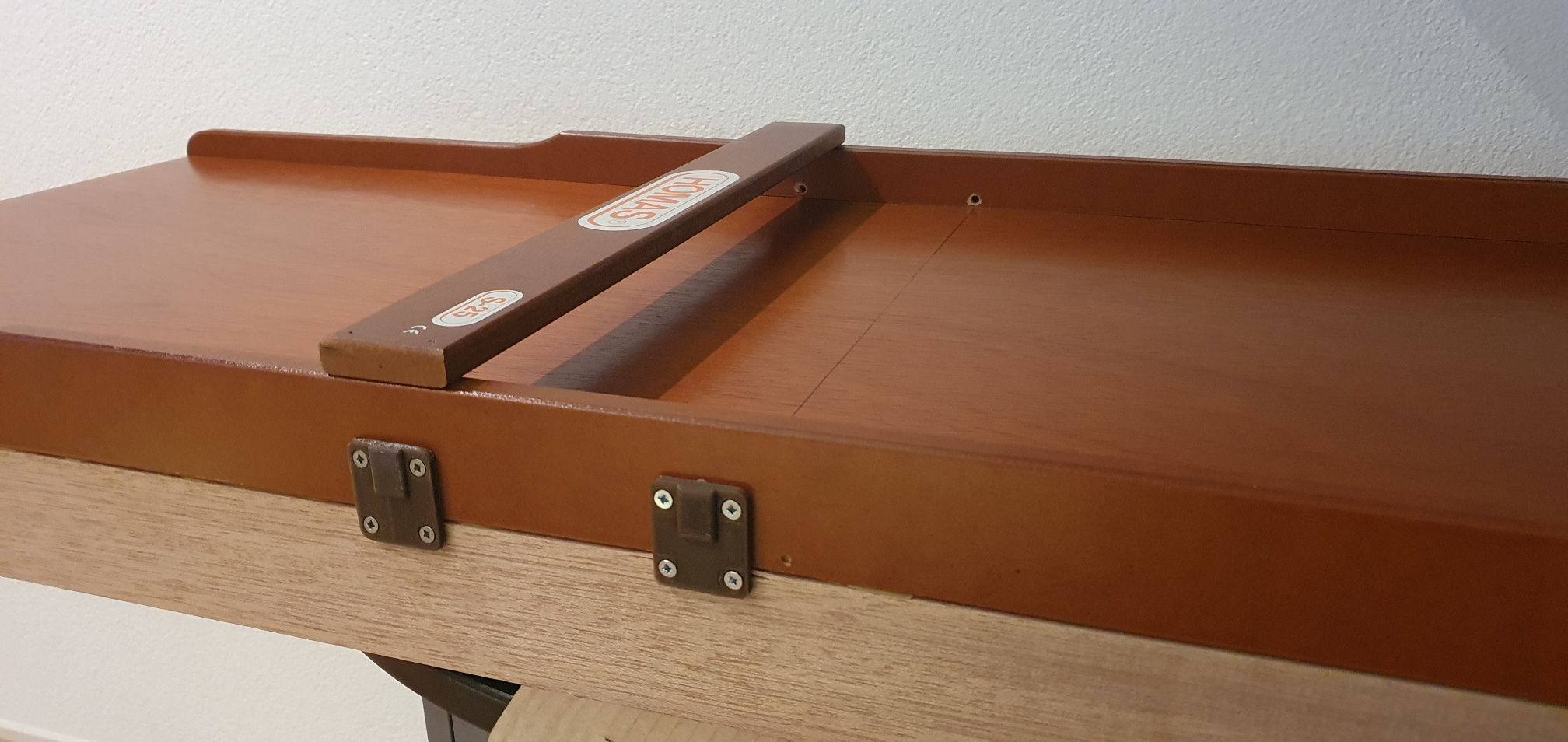
First I saw off the back of the original shuffleboard, because that's where the pucks have to fall into the bin. This became a disappointment, because the wooden planks between the ports are not attached to the bottom plate and therefore move in all directions during sawing. I tried sawing from different angles but it was a hassle. The result is therefore mediocre and if I ever build such a shuffleboard again, this has to be done differently.
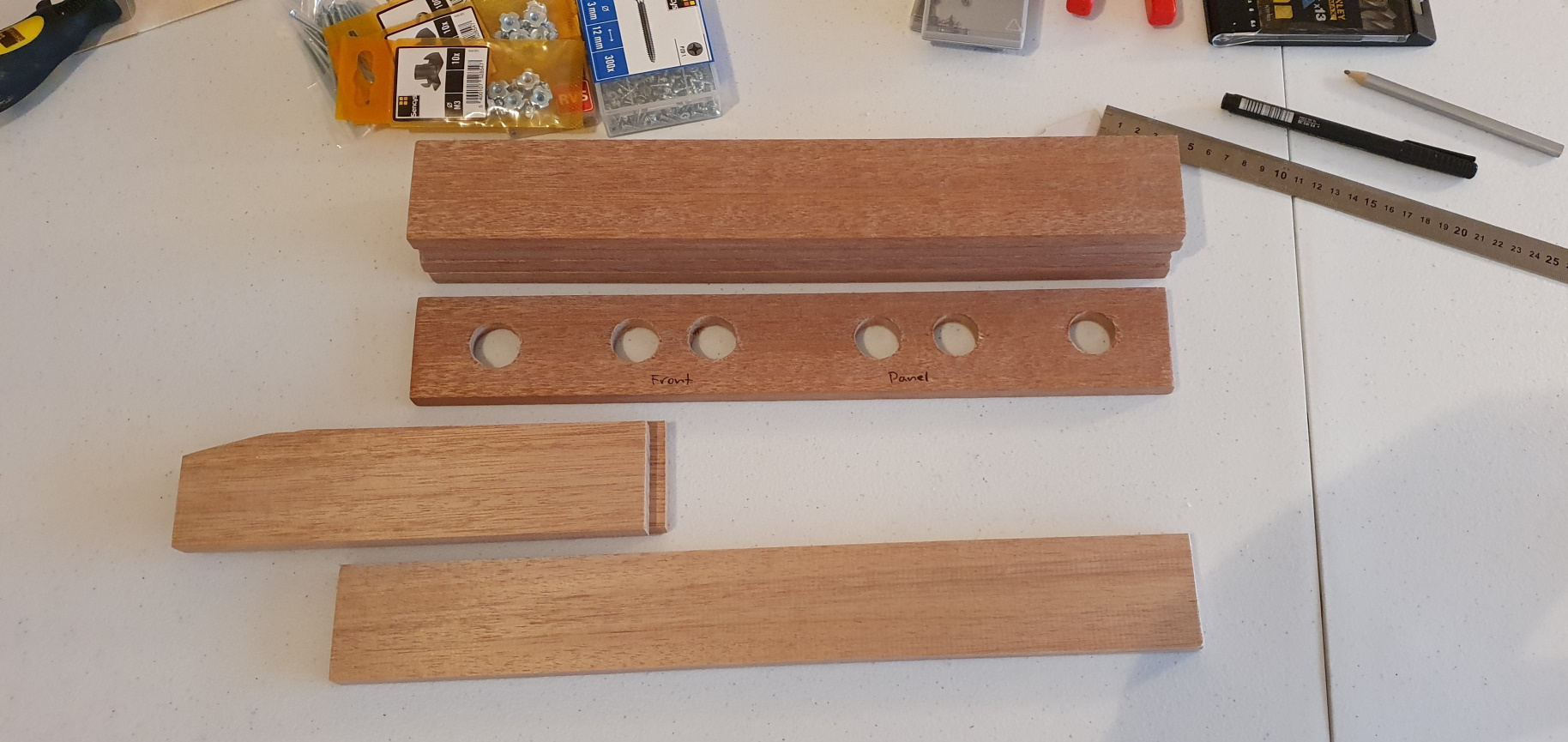
I sawed several 5.5 cm wide hardwood slats to size and prepared them with holes where necessary. I already attach some parts such as the speakers and cable trays to these slats. That is easier to do beforehand than when the frame is already put together.
With a strong wood glue I stick the "walls" together. This takes several days because they can't all be done at once and they have to be clamped for 24 hours to properly bond. To make it even more robust, I also put in some reinforcement corners. I printed these myself, because I was very enthusiastic about it, but in the future I might as well buy them. They are available from iron (sturdier) and it is not an expensive part. In the video above you can see the order in which the slats are mounted.
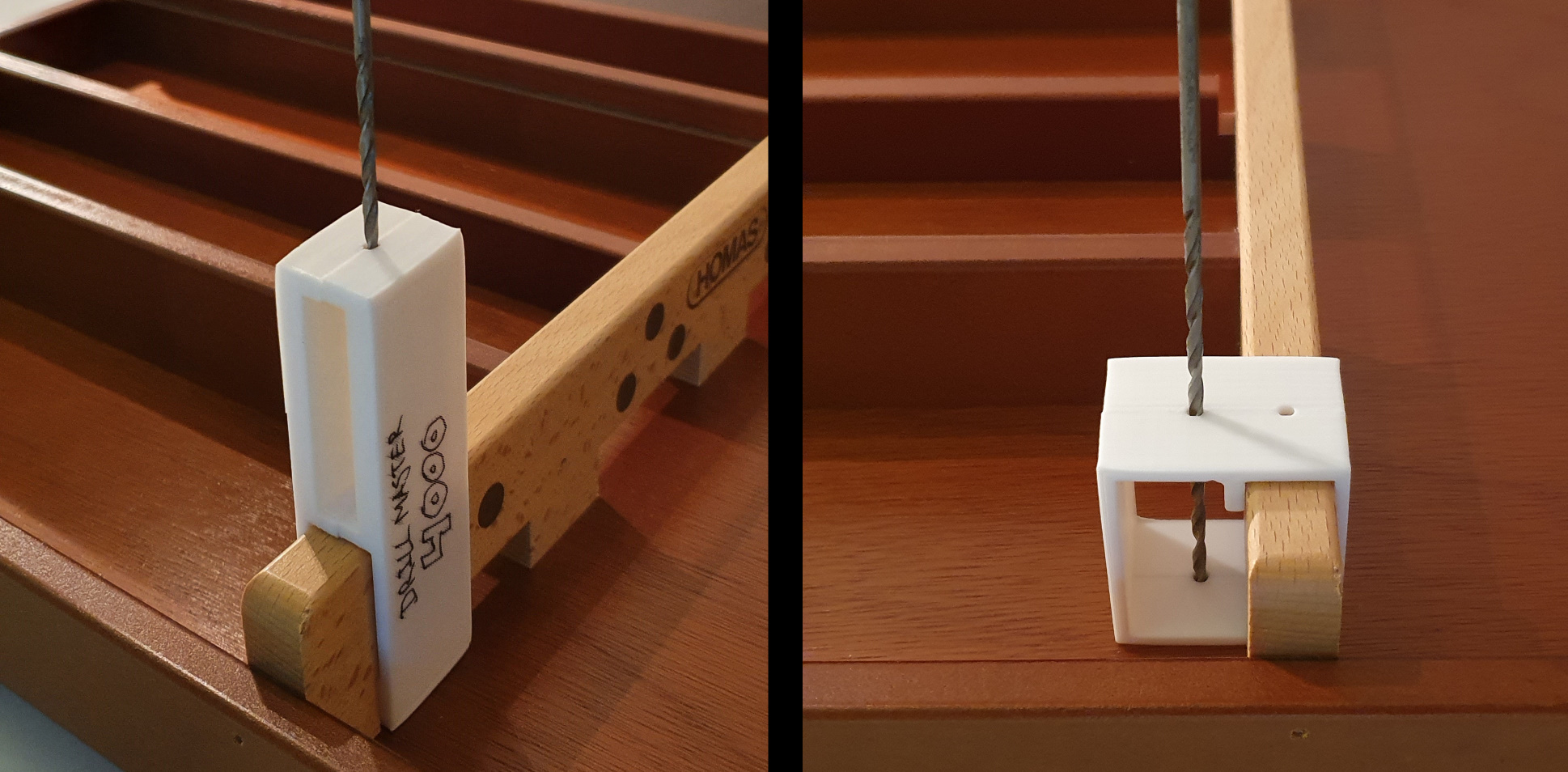
To drill the necessary holes in the gates, I made two rigs to guide the drilling. This way I know for sure that the holes are precisely in the right place and that they are drilled straight down. Unfortunately I don't have a drill press at home.
I attach the LEDs and the sensors with (again, 3D-printed) covers and mounting pieces.

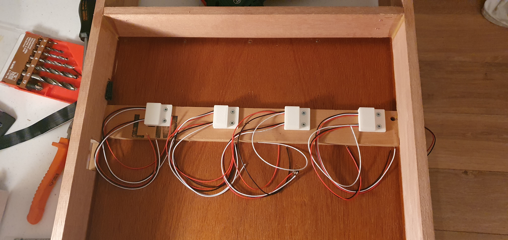
In my design I kept 10 cm between the two bridge sensors, because any closer and the light from one of the LEDs would cross over diagonally to the other sensor. Then both sensors would no longer work.
Of course, only after I had already mounted the sensors I got the idea that I could swap the LED and sensor of 1 pair so that the light from that LED would never reach the other sensor (then on the same side). The sensors could have been placed closer together, leaving more space on the board where pucks can land without being rejected. Let this be a tip for he who builds the next arcade shuffleboard.
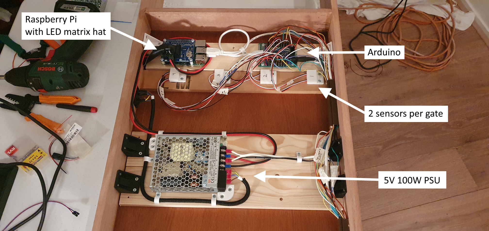
Now it is time to place and wire all the electronics: the PSU, Raspberry Pi, Arduino, Audio chip and the amplifier. And of course secure the wiring and put them neatly inside the cable trays.
The display was a matter of 3D printing and screwing/gluing together. This was easier said than done, because these are quite large pieces to print and it consists of 4 pieces that must fit together seamlessly. Quite a challenge for a beginner with 3D printing, but after 3 attempts I was satisfied with the result.
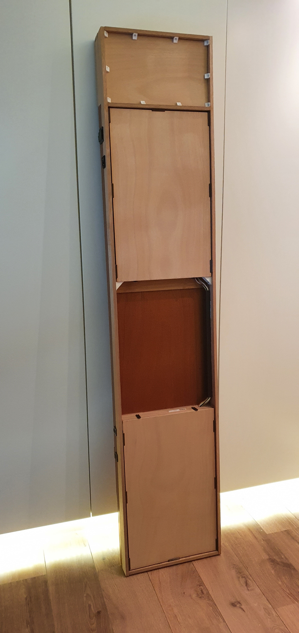
Finally, I closed the bottom with thin plywood sheets which slide in (again 3D printed) slots. These prevent damage to both the electronics and children's fingers, and can be slid open when needed.
The Programming
The software is written in C++, both on the Raspberry Pi and the Arduino. On the Arduino that is of course limited, because it is bare-metal programming (no operating system). For developing environment I use Visual Studio with the Visual Micro plugin. Visual Studio is already hands-down the king of development environments and can remotely build and debug a Linux application on the Raspberry Pi. With the Visual Micro plugin I can do the same on the Arduino and I don't need the Arduino IDE. This is not a requirement, the software can also simply be compiled and uploaded with the Arduino IDE.
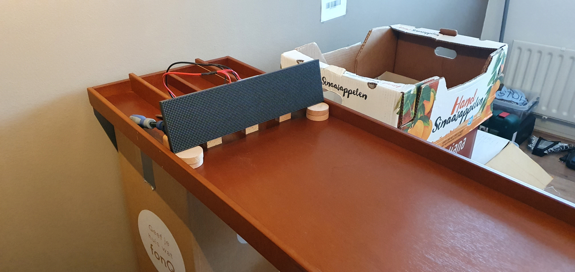
While the wooden frame is clamped for days, I'm working on the software in the mean time. I put together some of the electronics on my desk to develop and test the software.
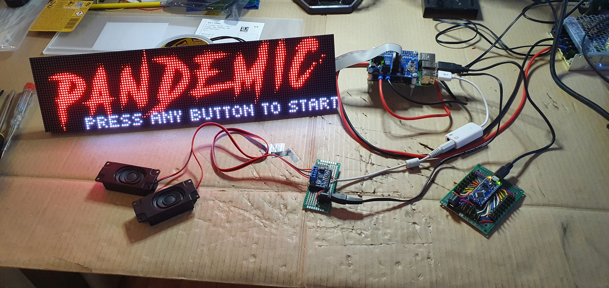
The Arduino software has 3 modes: Idle, Normal and Testing. These can be chosen by the main software (running on the Raspberry Pi). Idle mode is for startup (as long as the main software has not yet started) and causes the yellow button to flash to indicate that startup is underway. Normal mode monitors all sensors and reports events to the main software in simple messages such as "A puck went through port 2". Testing mode also monitors all sensors, but provides low-level reporting such as "Front Port 2 Sensor High". This is used for the system test function.
For communication over USB (serial) I use Protobuf. This is a lightweight and simple protocol and I already have experience with it, so it was quick to implement.
The main software runs on the Raspberry Pi and does most of the work. It consists of a number of state machines and has a lot of code around rendering the display video. I wrote this code myself, because it's quite a niche with a lot of demands like pixel perfection at low resolution (and it was fun). Also, the computing power on a Raspberry Pi is limited. For communication with the displays I used Henner Zeller's "rpi-rgb-led-matrix" library. This code can be found at github.com/hzeller/rpi-rgb-led-matrix and is well documented. For mixing the audio (music and sound effects) I use fmod.
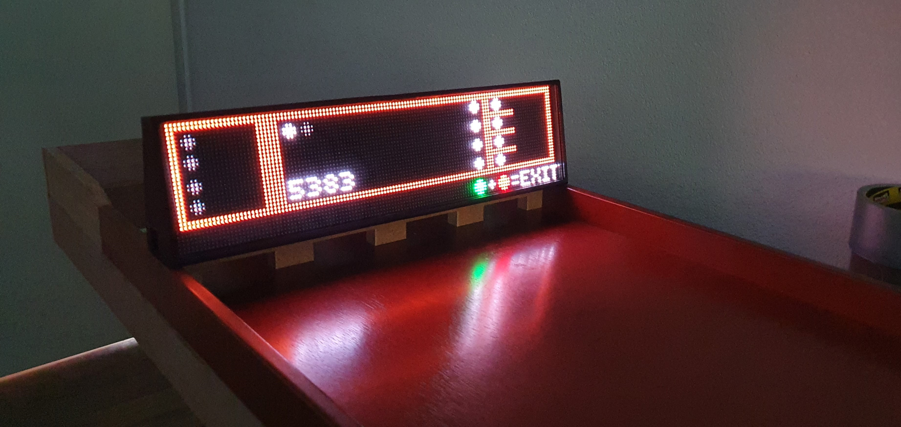
The software has a system test function with which all sensors are visualized. This is useful to check whether everything is working properly (after transport, for example).
You can download the software here for free. There are clear instructions in the README.md on how to compile the software and/or how to run it in a virtual machine (no hardware needed).
The software is not perfect. There may be some bugs and some things I should refactor to make it more maintainable. As an experienced software engineer and architect, I must warn you that the software is of hobby quality. It contains no (unit) tests. But this happens to be a hobby project, so that's fine.